1. Introduction
The one way slab can be defined as the type of slab in which the ratio of the longer span to the shorter span is greater than two.
Mathematically;
(Longer Span / Shorter Span) ≥ 2
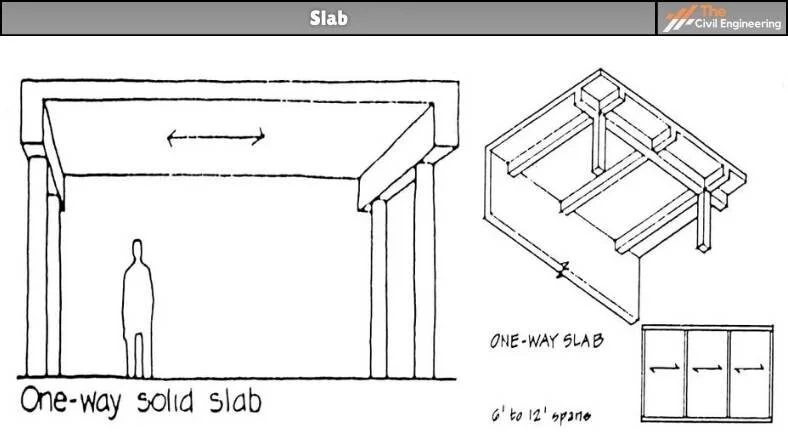
In other words, the one-way slab is supported by beams in such a way that the load is carried along one direction.
The shorter span of the one-way slab is provided with the main reinforcement while the longer span is provided with the distribution reinforcement.
Some of the prominent examples of one-way slabs are the cantilever slabs, chajjas, and verandahs.
* Points to Remember
a. Every two edge supported slabs are always one way.
b. All cantileverslabs are one way.
c. Slab containing supports on less than 4 sides can be designed as a one way slab.
2. Reinforcement Details of One Way Slab

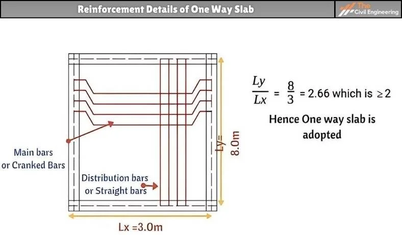
Figure 1: Reinforcement Details of One Way Slab
Figure 1 depicts the reinforcement details of a one-way slab.
As shown in the figure above, in the one-way slab, the main bars (cranked bars) are provided on the shorter side. While the distribution bars are provided on the longer side.
3. Design Considerations For One Way Slab
The design criteria as given by the ACI Code Specifications for the one way slab are as follows:
1. Minimum Slab Thickness
The minimum thickness of the slab to control deflection is given by ACI Code 9.5.2.1.
According to it, the specified thickness values are as follows:
a. For simply supported one-way solid slabs,
Minimum Slab Thickness = l/ 20
b. For one end continuous one-way solid slabs,
Minimum Slab Thickness = l /24
c. For both end continuous one-way solid slabs,
Minimum Slab Thickness = l / 28
d. For cantilever one-way solid slabs,
Minimum Slab Thickness = l /10
2. Span
The span requirement for the slabs is given by ACI Code 8.7.1.
According to it, if a slab rests on its support freely, the span length may be taken as equal to the clear span plus the depth of the slab but need not exceed the distance between the centers of supports.
3. Bar Spacing
According to ACI Code 7.6.5, the lateral spacing of the flexural bars should not exceed three times the thickness of 18 inches.
According to ACI Code 7.12.2, the lateral spacing of temperature and shrinkage reinforcement should not be placed farther apart than 5 times the slab thickness or 18 inches.
4. Maximum Reinforcement Ratio
The reinforcement ratio can be defined as the ratio of reinforcement area to gross concrete area based on the total depth of the slab.
5. Minimum Reinforcement Ratio
According to ACI Code 7.12.2.1, for the shrinkage and temperature reinforcement,
Slabs with grade 40 or 50 deformed bars = 0.0020 psi
Slabs with grade 60 deformed bars = 0.0018 psi
Slabs with reinforcements having yield strength greater than 60000 psi = (0.0018 x 60,000/ fy)
According to ACI Code 10.5.4, for flexural reinforcement,
Flexural Reinforcement must be greater than 0.0018 psi or shrinkage reinforcement.
4. Design Procedure of One Way Slab
a. Identifies the type of slab.
b. Determine hmin and round it to a higher 10mm multiple.
~ Should not be less than 110 mm for rooms
~ Should not be less than 75 mm for sunshades.
c. Determine the dead load that is acting on the slab.
Dead Load = Load per unit area x 1m width.
d. Determine the live load acting on the slab.
Live load = Load per unit area x 1m width.
e. Determine total factored load per unit strip (kN/m)
f. Determine moments. Moments can be determined either directly (simply supported) or by using coefficient for continuous slabs.
g. Determine effective depth.
d = h – (20 + (½)db)
db = 10, 13, 15 are generally used
h. Check the condition d ≥ dmin.
i. Calculate As required for 1m width.
j. Determine minimum/distribution/temperature & shrinkage steel.
k. Select diameter and spacing for main steel Analysis and Design of Slabs.
l. Check the minimum and maximum spacing
~ Generally, smin is nearly equal to 90mm
~ If the spacing is less than minimum increase the diameter of the bar.
m. For continuous slabs, curtail or bent up the +ve steel. For -ve steel see how much steel is already available. Provide the remaining amount of steel.
n. Determine the quantity of the distribution bar. Decide its diameter & spacing.
o. Check the shear of the slab.
p. Carry out detailing and show results on the drawings.
q. Prepare bar bending schedule in necessary conditions.
5. Complete Example of One Way Slab Design
We have provided you with this example in PDF format for your ease. Kindly download it and learn it. Thank You!
| Download Link | Download |
| Read Also: Building Substructure |


