In this article, we will discuss topographic surveying.
1. Introduction
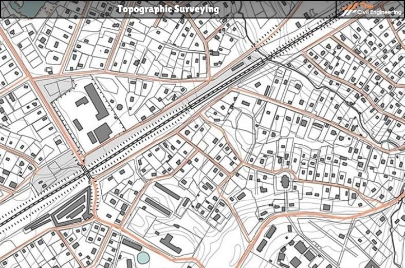
Topographic surveying is the process of determining the positions, both on plan and elevation, of the natural and artificial features of a locality for the purpose of delineating them by means of conventional signs upon a topographic map. By topography means the shape or configuration of the earth’s surface.
The basic purpose of the topographic map is to indicate the three-dimensional relationships for the terrain of any given area of land. Thus, on a topographic map, the relative positions of points are represented both horizontally as well as vertically. The representation of the difference in elevation is called the relief.
On a plan, the relative altitudes of the points can be represented by shading hachures, form lines, or contour lines. In addition to the relief, the topographic map depicts natural features such as streams, rivers, lakes, trees, etc. as well as artificial features such as highways, railroads, canals, towns, houses, fences, and property lines.
The topographic maps are very essential for the planning and designing of most engineering projects such as the location of railways, and highways, the design of irrigation and drainage systems, the development of water power, the layout of industrial plants, and city planning. Topographic maps are also very useful in directing military operations during a war.

2. Methods of Representing Relief
The system used for showing the relief on a topographic map must fulfill two purposes,
(i) the user of the map should be able to interpret the map as a model of the ground, and
(ii) it should also furnish definite information regarding the elevations of points shown on the map. Relief may be represented on a map by hachures, form lines, tinting, or contour Lines.
Hachures are a system of short lines drawn in the direction of the slope. For a steep slope, the lines are heavy and closely spaced, while for a gentle slope, they are fine and widely spaced. While hachures show the surface form, they do not furnish exact information regarding the heights. A contour line is an imaginary line on the ground joining the points of equal elevation. It is a line in which the surface of the ground is intersected by a level surface.
| Read Also: Theodolite in Surveying |
The relief on a topographic map is most commonly and accurately represented by contours. Form lines resemble contours but are not drawn with the same degree of accuracy. Each form line represents an elevation but has not been determined by sufficient points to conform standard of accuracy usually required by contours. Form lines are sometimes used on maps, intended for the purpose of navigation, to show peaks and hilltops, along the coast.
The relief or elevations may also be indicated by tinting. The area lying between two selected contours is colored by one tint, that between the two others by another tint, and so on.
3. Procedure in Topographic Surveying
The fieldwork in topographic surveying consists of the three parts
(i) establishing horizontal control as well as a vertical control,
(ii) locating the contours, and
(iii) locating the details such as rivers, streams, lakes, roads, railways, houses, trees, etc.
The establishment of the horizontal and vertical control system is the most essential part and is the first step in the topographic survey since the three coordinates of a point (i.e. two co-ordinates to locate it horizontally, and one co-ordinate in the vertical plane to the horizontal plane can be established or measured only with locating it vertically with respect to the datum) respect to well connected horizontal and vertical control systems.
(1) Horizontal Control
The horizontal control forms the skeleton of the survey from which contours and other details are located. When the area to be surveyed is small, the horizontal control may consist of one single station, and the distance and direction of each point can be measured with respect to this station. When the area is relatively large, the horizontal control may consist of a traverse or a series of connected traverses.
The traverses may be run with the help of a tape compass, plane table, or tape transit, depending upon the extent of the area. Sometimes, the length of the traverse sides is determined with the help of stadia measurements, especially when the land is uneven.
A stadia traverse is thus used in the survey of an uneven area of moderate size. On very extensive surveys, the horizontal control may be either a simple or a very elaborate triangulation system, with additional control being provided by traverses connecting the triangulation stations.
Secondary traverses are sometimes run with the plane table. In flat and densely wooded countries, where triangulation is impracticable or very expensive, the primary horizontal control may be established by precise traversing.
| Read Also: Contour Interval |
(2) Vertical Control
Vertical control establishes a framework with reference to which the elevation differences are determined. This control is very important since the topographic map must indicate the relief or the third dimension.
The object of the vertical control is to determine the elevations of the primary control stations or to establish bench _narks near them and at convenient intervals. High-order spirit level circuits are run to determine elevations accurately defining the position of all the control points.
Trigonometric leveling is often used to transfer elevations from precise leveling circuits to triangulation stations, these stations generally being located on high, commanding points, while the levels are run in so far as possible, over level or gently sloping terrain. The secondary vertical control is then established by determining the elevations of traverse stations or benchmarks near them. This can be established by the tacheometric method or by spirit leveling.
When the level is used, the elevations of control points can be determined by running circuits of levels, or benchmarks can be set in such positions that they can be seen from nearby horizontal-control points. For rough work, barometric leveling may be used.
(3) Locating Details
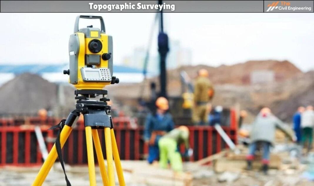
After having located or established the horizontal and vertical control, the detail is located from the control points by the measurement of angles and distances to those points which are to appear on the finished map.
The three coordinates of any point (or details) can be determined or computed by the measurement of
(i) direction of that point from the control point,
(ii) distance of the point from the control point, and
(iii) elevation of the point. Angles may be measured with the help of a compass or transit, or graphically by a plane table. The distance can be measured with a chain or a tape, or determined by tacheometric observations.
The elevation of the point may be obtained by hand level or the engineer’s level or maybe calculated from stadia or horizontal distances and vertical angles. The map is prepared by plotting first the control points and then the detail. The contour lines are drawn next and then the relief is depicted by means of conventional signs.
4. Use of Topographic Surveying
The topographic surveying is used for:
a. Preparing topographic maps.
b. It is used in constructing topographic (cross-sectional) profiles.
c. It is also used in establishing vertical and horizontal control for accurately defining locations.
Read More: Plane Surveying
Read More: Total Station in Surveying

